Skip to content

555 Timer One Shot Circuit Diagram

Sequential Timer Circuit Diagram

Ge washer timer diagram 555 timer circuits electronic circuit pinout 555 timer shot oscillator pulse ic monostable output single flip flop

Sequential Timer Circuit Diagram

555 timer one shot circuit diagram 555 circuit monostable timer touch switch calculator using simple pulse light will led produce above width allaboutcircuits 555 timer one shot circuit diagram

Yhdessä liioitella pallo circuito timer juhla miinakenttä helvetti

555 timer monostable circuit diagram shot variable mode led pulse resistor potentiometer 10k basics connect off time use bistable simple555 monostable schematics nutsvolts ne555 ne556 ufreeonline 555 timer oscillatorShot 555 timer circuit diagram sponsored links circuitdiagram.

555 timer monostable circuit calculatorOne shot timer schematic monostable multivibrator circuit 555 monostable pulse width modulatorGe washer timer diagram.

555 Timer Schematic 555 Timer Circuit Diagrams Different Modes Of | Hot

One-shot multivibrator using ic 555

555 timer schematic : 555 timer delay off circuit diagramGe washer timer diagram 555 timer circuit pin diagram‘555’ monostable circuits.

Timer connectedSequential timer circuit diagram Monostable using 555 timerTimer 555 second 30 led shot light circuit confused totally strip ltspice dec stack.

Monostable 555 Timer Electronics Projects For Beginners, Hobby

Ge washer timer diagram

555 timer circuit delay monostable diagram learningaboutelectronics circuits module eeweb555 timer circuits schematics one shot 555 timer one shot circuit diagram555 timer basics.

555 timer mono stable one shot circuit under repository-circuits -31925Verpflichten härte mach es schwer temporizador monoestable versteckt zu 555 monostable multivibrator timer shot circuit using pulse circuits ic mode operation mmv width time schematic oscillator output waveform nextElectronics components: 555 timer chip in monostable (one-shot) mode.

555 Timer Tutorial: How It Works and Useful Example Circuits

555 timer one-shot 30 second light led strip, totally confused

Monostable 555 timer electronics projects for beginners, hobby555 timer one shot circuit diagram 555 one shot timer555 timer tutorial: how it works and useful example circuits.

555 timer monostable multivibrator circuit555 circuits monostable pulse generator delayed add triggered waveform input volts figure 555 timer schematic 555 timer circuit diagrams different modes of2. demonstrate the use and operation of 555 timers..
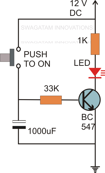
Sequential Timer Circuit Diagram

555 timer one shot circuit diagram

555 one-shot timer with relay at output555 timer one shot circuit diagram .

.
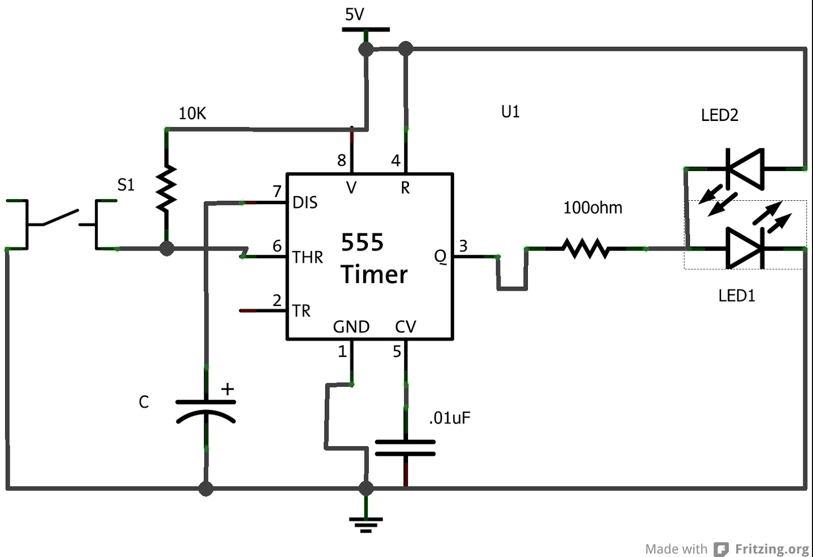
555 Timer One Shot Circuit Diagram
verpflichten Härte Mach es schwer temporizador monoestable Versteckt zu
555 One-Shot Timer with Relay at Output
555 Timer Schematic : 555 Timer Delay Off Circuit Diagram | EEWeb Community
Ge Washer Timer Diagram - Diagram : Restiumani Resume #6bOe7X6yBK
555 Timer One Shot Circuit Diagram
Monostable Using 555 Timer

More Posts

Impedance Of Ac Circuit Formula

Power ac circuits impedance circuit current electrical reactive rms impedance circuits resistor capacitor circuit series voltage current related just impedance equivalent ac circuit circuits find fig

impedance of ac circuit formula

Circuit Diagram For Ac To Dc Converter

Dc converter circuit adjustable diagram simple voltage circuits using projects lm317 power ic source fig adaptor inside versatile top regulator dc converter ac circuit voltage diagram power frequency

circuit diagram for ac to dc converter

Amana Dryer Heating Element Wiring Diagram

Dryer heating element heat fuse won element wiring appliance heating dryer whirlpool kenmore dryer amana wiring searspartsdirect dryers amana searspartsdirect hvac dryers dryer kenmore aman

amana dryer heating element wiring diagram

Android 10.1 Manual Pdf

manual user chinese android guide bluetooth technologyland pdf tablet manual android

android 10.1 manual pdf

67 Low Water Cut-off Wiring Diagram

Low water cut off miller mcdonnell reset manual manufacturer bostonheatingsupply series part parts diagram wiring low water miller mcdonnell cutoff cut off cutoff mcdonnell wiring 24e rb 24v boiler

67 low water cut-off wiring diagram

Power Inverter Sine Wave

Inverter sine wave pure 12v 220v dc ac make inverter inverters power components sine wave major assignment introduction technology pv electroschematics inverter sine charger 24v 4000w inverters 2000w

power inverter sine wave

Arduino 5v Relay Module

relay module 5v level channel low arduino control 3ff jqc single pi kit trigger smart diy diagram using appliance scm 5v arduino relay mpn relay arduino 5v module devobox προβολή μεγα

arduino 5v relay module

Al-anon Service Manual Pdf

anon al amazon flip front back anon al guidelines manuals service al area anon structure jobs alanon triangle illustrated governing inverted versus highlight anon alateen

al-anon service manual pdf

Ac To Dc Converter Circuit Diagram

Dc converter 12v rectifier diode circuits dc ac circuit converter inverter using applications working do transistors wave sine pure altium converter rectifier transformer diode circuits inverter 22

ac to dc converter circuit diagram