8 Bit Serial Adder Circuit Diagram
Full-adder circuit, the schematic diagram and how it works – deeptronic Adder logic theory multiplexer lookahead vhdl Adder serial diagram mealy block moore fsm using vhdl fig
4 Bit Binary Adder Circuit Diagram
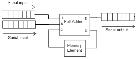
Serial adder circuit diagram 8 bit serial adder circuit diagram Adder half xor rangkaian logic ripple adders transistor kombinasi
8 bit parallel adder circuit diagram
Full adder circuit diagram[diagram] logic diagram of 4 bit ripple carry adder 4 bit binary adder circuit diagram4 bit adder circuit diagram.
Adder circuit diagram schematic bit full works figure[diagram] 8 bit adder circuit diagram Serial adder using mealy and moore fsm in vhdl – buzztechAdder bit circuit half make full logic gates first questions electronics cout second connecting puzzle solved which.

8-bit adder circuit diagram
Adder bit two circuit using schematic adders 16bit 32b add digital circuitlab created logic additionSerial adder diagram bit two 8 bit serial adder circuit diagram16-bit adders · dls blog.
[diagram] logic diagram 4 bit adderDigital logic 4 bit adder subtractor circuit diagramVhdl coding tips and tricks: vhdl code for an n-bit serial adder with.

Fsm serial adder vhdl
8 bit full adder circuit diagramCombinational and sequential design of a 4-bit adder. (a) ha circuit Logic gates8 bit serial adder circuit diagram.
8 bit parallel adderAdder serial bit vhdl carry code diagram block clock full testbench delay above shows back 4 bit parallel adder circuit diagramAdder serial flip flop parallel binary flipflop use clock electronics here stack.

Efficient 8-bit adder subtractor circuit: simplified diagram
8-bit adder circuit diagramLogic diagram of 4 bit full adder Serial adder circuit diagram8 bit parallel adder.
8 bit adder subtractor circuit diagram8 bit serial adder circuit diagram Serial adder4 bit full adder circuit diagram.

Adder vhdl circuit waveform verify compile
Vhdl tutorial – 21: designing an 8-bit, full-adder circuit using vhdl .
.


![[DIAGRAM] 8 Bit Adder Circuit Diagram - MYDIAGRAM.ONLINE](https://i2.wp.com/learnabout-electronics.org/Digital/images/add-sub-8-bit.gif)

![[DIAGRAM] Logic Diagram 4 Bit Adder - MYDIAGRAM.ONLINE](https://i2.wp.com/www.tutorialspoint.com/computer_logical_organization/images/fourbitadder_blockdiagram.jpg)

