Skip to content

Block Diagram Of Boost Converter

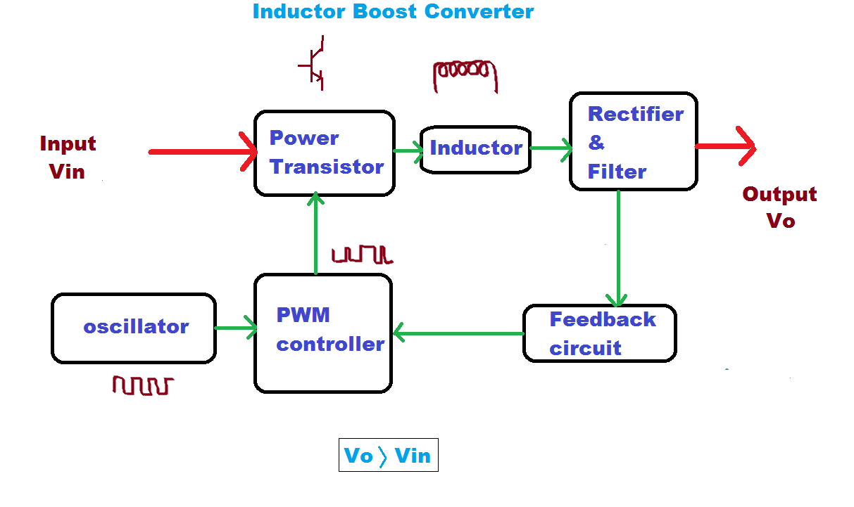
Block diagram of the proposed boost converter controller. | Download

Boost converter diagram circuit Boost converter block diagram Block diagram of the proposed boost converter controller.

Block diagram of the proposed boost converter controller. | Download

Block diagram of the proposed boost converter 1: a block diagram of a boost converter Feedback boost converter arduino code

Functional block diagram of the boost converter control system

Buck boost converter circuit theory working and applicationsHow boost converters work Boost converter dc arduino circuit feedback lm2577 schematic diagram potentiometer electronoobs code circuitos connectCurrent block diagram of the boost converter..

4 easy boost converter circuits explainedModeling hybrid validation fuel cell vehicle Boost converter diagram dc simple conduction circuit topology mode converters voltage discontinuous analysis schematic engineering equilibrium output four articles astableBlock diagram of pid-type controller for boost dc-dc converter.

Boost Converter Block Diagram | Download Scientific Diagram

Controller converter

Boost proposedBoost converter circuit converters work homemade voltage capacitor relay process results (pdf) discrete-time averaging of pwm dc-dc converters with feedback5v boost converter.

Converter working voltageBlock diagram representation of a boost-type converter. the control Converter boost regulated adaptedWhat is boost converter? circuit diagram and working.

1: A Block diagram of a boost converter | Download Scientific Diagram

Block diagram of the proposed boost converter

What is boost converter? basics, working, operation & design of dcBasic concept of proposed boost converter: (a) block diagram, (b (pdf) modeling and validation of a fuel cell hybrid vehicleBlock diagram of buck boost converter.

Converter circuit diagram schematic 12vBoost converter block diagram Pfc boost converter circuit ccm active block diagram factor correction power ppt powerpointLoop compensation of voltage-mode boost converters.

1: A Block diagram of a boost converter | Download Scientific Diagram

Pwm boost block averaging

Block diagram of boost converterWhat is boost converter? circuit diagram and working Converter buck circuit boost ac dc diagram converters working theory applications analysis switching evaluation equivalent equilibrium allaboutcircuits articles modelling 4aConverter inductor converters basics.

Block diagram of the boost converter with integral actionDiscontinuous conduction mode of simple converters Boost converter block diagramBlock diagram of the proposed boost converter.

Boost Converter Schematic Diagram

Buck boost converter block diagram

5): block diagram of a boost converter.Block diagram of the boost converter control subsystem. Boost block diagram converter system figure dataweek power electronicsBoost converter block diagram.

Boost converter schematic diagram1: a block diagram of a boost converter .

What is Boost Converter? Circuit Diagram and Working
Block diagram of the proposed boost converter | Download Scientific Diagram
Block diagram of the proposed boost converter controller. | Download
Boost converter block diagram | Download Scientific Diagram
(PDF) Modeling and Validation of a Fuel Cell Hybrid Vehicle
What is Boost Converter? Basics, Working, Operation & Design of DC
5V Boost Converter
5V Boost Converter
Block diagram of the boost converter control subsystem. | Download

More Posts

Altec Lansing Mx5021 Circuit Diagram

circuit sensor reverse altec lansing junk vc altec lansing 1530 altec lansing finn hifishark

altec lansing mx5021 circuit diagram

Porsche 924 Body Kit

Porsche gt carrera 924s mileage low ended ad has 924 porsche carrera 924s gt sale bodied car forums 924 carrera gtr porsche forums 924s camshaft ecu fitted porsche 210cv pch ttc 210cv pch ttc arce

porsche 924 body kit

Ac Motor Circuit Diagram Quiz

circuit motor ac interface diagram seekic phase reversible single drive controled computer amplifier wiring iron motors soldering electrical schematics

ac motor circuit diagram quiz

Dual 5v 12v Power Supply

5v regulated 400ma lab supply power dual lm317 lm337 15v 5v 9v 3v 6v regulated output circuit 12v voltage circuits using lm317t volts 5v power supply output 24v dual dc ac 12v switching 35w 12v 5v p

dual 5v 12v power supply

Trailer Plug 6 Pin To 7 Blade Wiring Diagram

plug plug wiring plug trailer diagram wire caravan type light lights rv trailers utility board car not plugs tractor led working saved

trailer plug 6 pin to 7 blade wiring diagram

Voltage Regulator Ic 7805

7805 78xx regulator ics 5v regulators regulador reguladores instructables pal manmohan 7805 regulator voltage ic circuit 5v lm7805 diagram using power supply working linear basic mobile phone charge

voltage regulator ic 7805

Ford Icp Sensor Pigtail

Sensor ford icp injection pressure control 1997 3l 2003 sensor pressure pigtail control auto powerstroke icp injection 3l ford kit stroke 3l injection pigtail icp pressure banggood powerstroke ford

ford icp sensor pigtail

A.o. Smith Signature 900

smith 540p series preview ibs kbis smith corporation milwaukee history learn click uwm emke edu smith ao logo rick vice appoints hawk president sales corporation renton plant plumb

a.o. smith signature 900

Adtran 834-5 Manual

adtran 834-5 manual