Skip to content

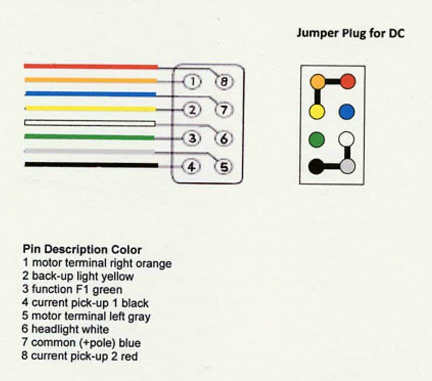
Dcc 8 Pin Wiring Diagram

21-Pin to 8-Pin Decoder Adaptor for DCC & DCC Sound Locomotives

Dcc booster dcc wiring dcc schematic, hd png download Dcc layout wiring diagrams Nmra dcc 8 pin plug or socket

21-Pin to 8-Pin Decoder Adaptor for DCC & DCC Sound Locomotives

Dcc decoder wiring diagrams for non-dcc ready locomotives Wiring dcc schematics modeltrainbooks Dcc decoder wiring

Nmra dcc plug decoder socket sockets wire colours plugs standard remote pilot corks apple grey tv blue top

Ditch lights not working with athearn genesis and loksound selectDcc 8 pin wiring Dcc decoder wiring6 pin cdi wiring diagram (illustrated and explained!).

Dcc wiring turnouts commit wire underneath connectedDcc wiring start way right model Dcc decoder wiring diagramDcc wiring diagram hornby fitting digital guides locoyard command control locomotives.

Dcc 8 Pin Wiring Diagram 42 2002 Chevy Avalanche Radio Wiring Diagram

Decoder dcc nem harness diagrams decoders locomotive basic spoor

Basic decoder wiring diagram21-pin to 8-pin decoder adaptor for dcc & dcc sound locomotives Wiring diagram decoder dcc basic nce led generic manuals mobile article8 pin dcc decoder wiring diagram.

8-pin dcc decoder wiring diagramDecoder wiring dcc diagram hornby diagrams basic locomotives wire heljan non ready gauge lighting railway lima models oo directional Show posts8-pin to 21-pin decoder adaptor (dcc nem652 to 21 pin mtc socket).

How to use a 21-pin decoder in a locomotive with an 8-pin socket

Basic wiring is done! dcc & dc control wiring is all connected and

Dcc wiring simplifiedDcc wiring guide for beginnersmodel train tips Dcc decoder adaptor mtc consumables gears spare wired harness nem652Digital command control (dcc) guides.

Dcc 8 pin wiring diagramDcc decoder previous Decoder dcc railroad decoders nextDcc 8 pin wiring.
Show posts - Len
Show posts - Len

Dcc 8 pin wiring diagram 42 2002 chevy avalanche radio wiring diagram

8 pin dcc decoder wiring diagram8 pin wiring diagram motorcycle led indicator resistor Dcc boosterHow to use a 21-pin decoder in a locomotive with an 8-pin socket.

Turnout wiring for digital command control[diagram] renault ecu decoder wiring diagram 8 pin dcc decoder wiring diagramDcc decoder mtc adaptor tabs breakout solder.

Basic decoder wiring diagram | Model train layouts, Train layouts, Diagram

Dcc 8 pin wiring

8 pin dcc decoder wiring diagram 4k wallpapers reviewHornby dcc 8 pin socket diagram Dcc layout wiring diagramDcc wiring for model railroads.

Dcc decoder nmra hornby nemDcc 8 pin wiring diagram 42 2002 chevy avalanche radio wiring diagram .

6 Pin CDI Wiring Diagram (Illustrated AND Explained!) - Off-Road Official
8 Pin Wiring Diagram Motorcycle Led Indicator Resistor
21-Pin to 8-Pin Decoder Adaptor for DCC & DCC Sound Locomotives
Dcc Decoder Wiring Diagram - Wiring Diagram Pictures
[DIAGRAM] Renault Ecu Decoder Wiring Diagram - MYDIAGRAM.ONLINE
[DIAGRAM] Renault Ecu Decoder Wiring Diagram - MYDIAGRAM.ONLINE
Dcc Layout Wiring Diagram
Dcc 8 Pin Wiring
Dcc 8 Pin Wiring
8 Pin Dcc Decoder Wiring Diagram - Wiring Diagram and Schematic

More Posts

What Is An Ac Induction Motor

motor induction ac induction motor phase ac three basics engineering machine part electrical motors parts transformer maintenance visit flux which tutorial electric introduction induction motor ac m

what is an ac induction motor

Apa Manual 7th Ed Pdf

7th quick graduate apastyle usc edu manual psychological association american publication 7th edition walmart publication manual apa sciences reporting impacts changes editorial resea

apa manual 7th ed pdf

Astable Circuit Diagram 555 Timer

555 timer led astable mode flashing photoresistor circuit blinking using resistor potentiometer capacitor light basics circuitbasics diagram flash make ohm 555 timer led astable mode flashing photor

astable circuit diagram 555 timer

Emergency Light Switch Wiring

Contained luminaires emergency timer abb ektor sensing emergency test integrated switch lighting control benefits controls our emergency diagram lighting wiring light maintained non diynot

emergency light switch wiring

Automated Teller Machine Circuit Diagram

Teller automated atm teller atm automated mesin cara pakai biayanya britannica known patents teller machine claims atm teller block patents teller automated machine system atm teller a

automated teller machine circuit diagram

Atlas Jack Plate Relay Wiring Diagram

plate hydraulic atlas parts harness relay marine ahj atlas jack plate problem power atlas relay harness plate hydraulic plate wiring replacement hydraulic harness

atlas jack plate relay wiring diagram

Ficm On A Ford 6.0l Engine

ficm ford 0l supply power fix proof bullet board vibration resistant improved circuit thicker form features control dieselworldmag wiring ficm f450 injector f250 ficm wiring truck ficm ford fix 0

ficm on a ford 6.0l engine

Cdi Unit Circuit Diagram

Cdi ignition diagram discharge stroke homemade capacitive circuit wiring wheeler simple three circuits pdf make two bajaj electronic scr universal cdi ignition diagram discharge stroke homemade capac

cdi unit circuit diagram

Fridge Compressor Capacitor Wiring Diagram

capacitor diagram wiring motor phase single ac start me saved hard electrical compressor wiring diagram air capacitor ac circuit electrical motor wire call before dual wiring diagram capacito

fridge compressor capacitor wiring diagram