Design A 4 Bit Adder Subtractor
Binary adder subtractor circuit 4 bit adder subtractor circuit diagram 4 bit adder subtractor circuit diagram
4 Bit Adder Circuit Diagram - Wiring Draw
4 bit adder subtractor verilog 4-bit binary adder-subtractor Block diagram for 8-bit adder/subtractor using set
Digital logic
Make adder subtractor bit carry verilog binary using ripple 4bit want subtraction addition operation output hdl has value which4 bit adder subtractor circuit diagram Circuit design 4 bit parallel adder subtractor with bcd 7 segment_group4 bit adder circuit diagram.
Design a 4 bit adder subtractor circuit4 bit adder subtractor truth table Digital logic design: binary parallel adder/subtractorAdder subtractor bit circuit logic overflow diagram detection designing questions digital.

Digital logic
4 bit adder subtractor circuit4 bit adder subtractor circuit diagram Logisim adder full bit circuit subtractor technologyAdder subtractor add bit binary logic full using subtraction tutorial adders sub combinational electronics circuits.
4 bit binary adder circuit diagramBinary adder/subtractor 4 bit binary subtractor circuit diagramLogic adder subtractor parallel binary circuit bit diagram control signal mode digital determines which has.

8 bit adder subtractor circuit diagram
All about technology: digital design : making a 32 bit adder/subtractorVhdl programming: design of 4 bit adder cum subtractor using structural Design 4 bit parallel adder and subtractorVerilog subtractor.
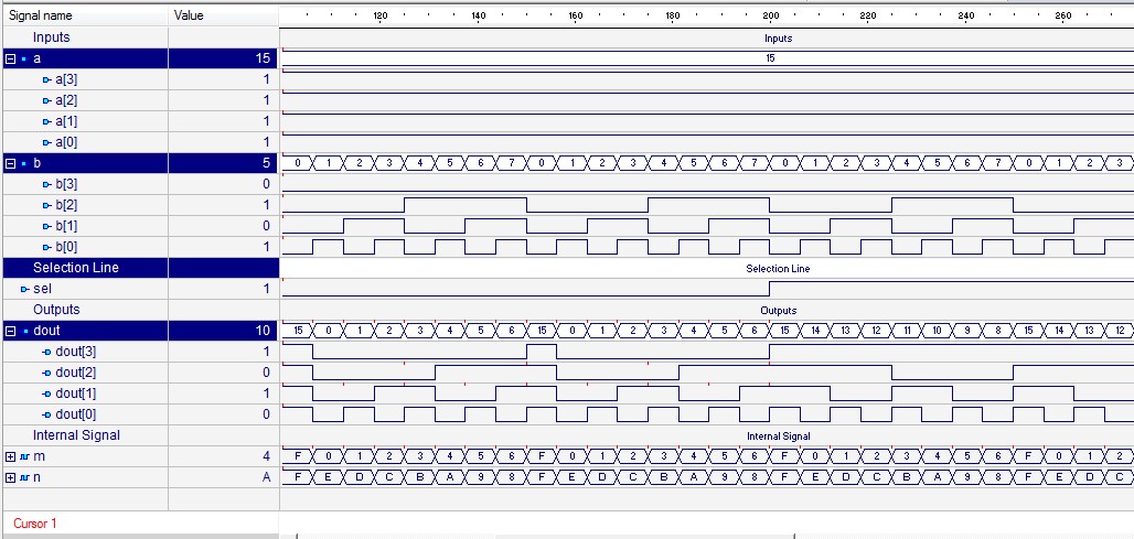
4 bit adder circuit diagram[diagram] 4 bit subtractor logic diagram Adder subtractor bit alu binary if gates chapter performs ppt powerpoint presentation xor inverters programmable actAdder bit subtractor verilog using vhdl structural code waveform modeling gate cum full xor output style 4bit programming.


